Increase machine availability by monitoring hydraulic power units in test rigs

Goal of the project
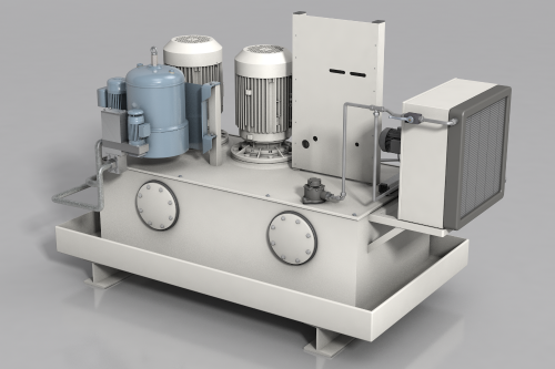
Something we are all too familiar with – often the most inconspicuous things have the biggest impact. This is true of hydraulic power units. They are the drive units in hydraulic systems and convert mechanical energy from an electromotor or combustion engine into hydraulic power. This function makes the unit the heart of a hydraulic system. If the hydraulic power unit fails, the entire process comes to a standstill and high costs arise for failure, replacement and disposal.
This is exactly where condition monitoring comes in: the “vital” components of the hydraulic power unit are constantly monitored to detect possible defects as early as possible. For example, on a pulse pressure hydraulic test rig, pressure sensors are subjected to an “accelerated service life test”. Other measured values, such as temperature in the tank, filling level or vibration data of the pump, provide information about the condition of the system. As a result, unplanned downtimes can be prevented, which in turn makes maintenance easier to plan and increases machine availability.
Prevention of delivery delays |
Cost savings by not using a redundant replacement pump |
Optimised |
|
On average, customers achieve: |
||
|
95% less frequent oil level checks |
€ 2,000 Savings in material and |
100% ROI from |
Hydraulic monitoring offers you the following advantages
Continuous monitoring of a hydraulic power unit enables a rapid response to changing measured values. Numerous components and measured values play a crucial role in assessing the condition of the system. The moneo condition monitoring tool records the measured values and takes actual wear into account. In the running process, for example, moneo enables continuous monitoring of the system pressure, the tank fill levels, tank temperatures, return temperature and the vibrations on the pumps.
moneo simultaneously records the pump operating hours and the temperature difference between the tank contents and the return line. Automated alarm management immediately triggers a message in the event of deviations, thereby enabling a quick, preventive response and, if necessary, timely maintenance. Monitoring hydraulic power units makes a considerable contribution to improving the availability, efficiency and safety of the system.
Value proposition
|
|
|
Continuous check-up: Comprehensive condition monitoring of the hydraulic power unit
To monitor a hydraulic power unit and make the production process transparent, moneo first permanently records the necessary sensor data on the individual components. The data provides information about the condition of the unit. The temperature and fill level must be checked continuously and oil must be topped up when required, as the unit must never run dry. The temperature in the return line is also an important factor within the hydraulic power unit. If the value exceeds 62 degrees, the unit switches off and the entire system fails.
The moneo condition monitoring tool also monitors the vibration of the pump that pumps the oil through the system. The hydraulic filters used must also be monitored and cleaned or replaced regularly, as it is difficult to prevent dirt from entering this type of system. The differential pressure provides information about the degree of soiling of the filters. Maintenance work like cleaning the hydraulic filter can therefore be carried out at the optimal time. Cyclical monitoring is no longer required.
- moneo enables extensive analysis and evaluation of numerous components and individual visualisation of separate process values.
moneo simulation video
Automated maintenance planning for a hydraulic power unit
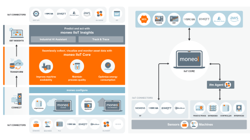
The complete solution for the Industrial Internet of Things (IIoT) featuring ifm sensors and moneo software offers a wide range of application options and interfaces to various systems to support you in automating processes. Data processed in moneo can be output using various protocols, such as MQTT and OPC UA, and integrated into your individual successor system.
To be able to react to changes in the unit as quickly as possible, the SFI (shop floor integration) interface allows warnings and alarms to be forwarded directly to your SAP. For example, if the hydraulic oil level in the tank drops or the temperature in the unit rises, the maintenance engineer is informed of the critical change via an email notification or message in SAP PM. If warnings are issued during the production process, the interface allows the maintenance engineer to inspect the hydraulic unit and, if desired, to automatically order the necessary components, depending on the customer’s wishes. The required components and spare parts are available promptly while simultaneously reducing inventory cost.
ifm also offers the necessary interfaces to save your data in the cloud and use it for further analysis if necessary.

- moneo
MQTT or OPC UA →AWS, Azure, SAP - SAP Integration
SFI (shop floor integration) →SAP PM - Alarm
email notification (threshold) - Spare parts
automatic ordering through SAP - Cloud and on-premises
possible with the cloud and on-premises solutions
How to install hydraulic power unit monitoring
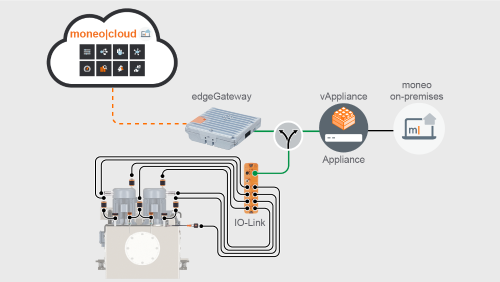
To monitor the numerous components and relevant measured variables of a hydraulic power unit, moneo is installed on a central server, or you can use moneo as a cloud application. For local server installation, we offer the ready-to-use vAppliance that can be installed in your virtualisation environment. You can also use the moneo Cloud by means of an edge gateway.
The necessary measured values are recorded via the sensors. This requires a vibration sensor and an inductive sensor on the pump to measure speed and temperature. Existing fill-level sensors can also be integrated or installed on the tanks.
For filter monitoring, pressure sensors are also used to determine the differential pressure. Using the IO-Link master, the sensor values are sent to moneo for evaluation and visualisation. Warnings and alarms about exceeded threshold values can be sent automatically as emails – allowing for a quick response. There is also the option of using existing sensors in the system and picking up the analogue values via the Y path i.e. a retrofit. This means a minimal redesign and minimal costs for installing hydraulic monitoring.
The system’s various sensor data provides important information about the condition of the hydraulic power unit. By preparing and analysing the data in moneo, unforeseen downtimes can be avoided. This improves machine availability and makes maintenance measures easier to plan, which in turn cuts costs.

System structure
- IO-Link master (VLAN)
- IO-Link vibration sensor
- IO-Link inductive sensor
- IO-Link speed sensor
- IO-Link temperature sensor
- IO-Link level sensors
- IO-Link pressure sensors (differential pressure)
- Analogue sensor values → Y path (retrofit)
moneo software
- Historical data
- Visualisation
- Monitoring
- Alarm function
- Threshold violations via SFI to SAP