- SD flow meters
- Setup and support
- Installation guidelines
Air flow meters | Installation guidelines
For best performance of the SD compressed air flow meters, please adhere to the installation guidelines below. More details are avaialble in the Operating manual found on the product datasheet page.
For more information, see our air flow meter products page or device configuration and programming resouces.
Straight pipe runs
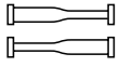
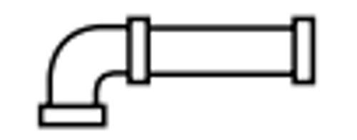
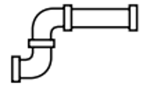
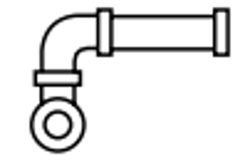
The calorimetric measuring principle is affected by turbulence in the flow stream. Therefore, the most repeatable measurements occur in laminar and uniform flow. The following table shows recommended straight piping runs after various interferences.
| Interference | Straight pipe runs to the sensor | |
|---|---|---|
 |
Changes to the pipe diameter | 10 x pipe diameter |
 |
90° elbow | 10 x pipe diameter |
 |
Two 90° elbows in the same plane | 15 x pipe diameter |
 |
Two 90° elbows in different planes | 25 x pipe diameter |
 |
Valve | 40 x pipe diameter |
Direction of flow
The thermal measuring principle does not provide the ability to determine which way the air is flowing. However, direction of flow is important for the units which are pre-mounted on threaded pipes (SD6xxx, SD7xxx and SD8xxx). These units have a directional arrow on the mounting pipe and when properly mounted, this ensures there is enough straight pipe run leading into the sensor to provide reliable measurements.
Orientation of the sensor
Assuming enough straight pipe runs are in place, the orientation of the SD sensor family is very flexible. All orientations shown in the image are acceptable except when the unit is installed with the pipe to the left of the sensor head (bottom right image). The SD is designed so that one of the probes is heated (the bottom probe in the image). With the heated probe on the bottom, it can influence the flow measurement.
Special requirements for installation of SD1540
The SD1540 can be installed in pipe sizes up to 10" in diameter using the E40195 weldable adapter. Alignment of the weld fitting on the pipe is critical to accurate flow measurements.
- Drill a hole in the pipe for the weld fitting and remove all burrs.
- Align the fitting so that the mark is no more than ± 2° offset from the pipe axis.
- Ensure the adapter is vertically in the pipe and does not extend into the pipe.